(1/15) Tutorial thread on how I made a Worms style procedural level generator, with visual examples and names of image processing algorithms being used for each step. Links to resources on the algorithms are at the end. While I am using Unity engine, the level generator code is standalone C#, and I hope to write this in a way that is useful for any language. My focus is going to be on the actual steps being taken, and less on the programming.

(2/15) First off, a small bit about the 2D Worms games. They feature destructible levels comprised of bitmaps, on which characters take turns trying to eliminate the enemy team(s) with a variety of weapons. For speed reasons, it is desirable to separate the visual aspects of terrain from the collision data. For this reason we will generate the collision data first and then make the visuals later. Visuals will not be covered in this tutorial.
Here is an example of a Worms: Armageddon (PC Release 1999) level:
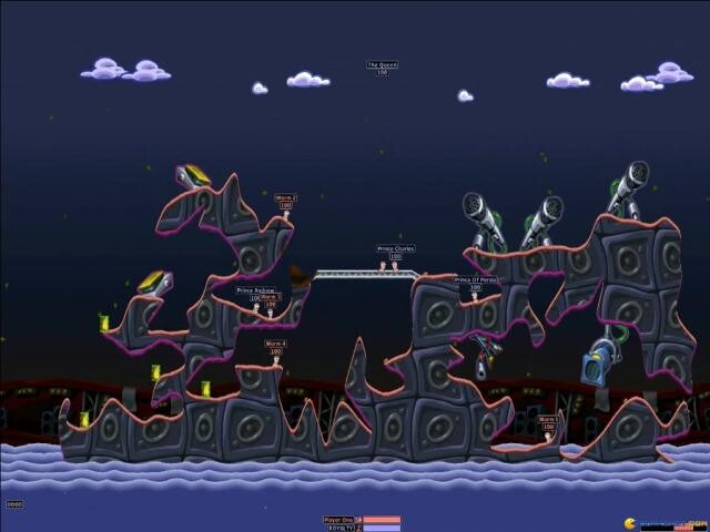
(3/15) Our final collision data will be made of a 2D boolean array. (C# bool[,]) Each x/y coordinate in our array will represent a single pixel of our level being solid (true), or not (false).
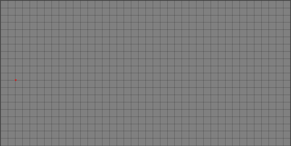
But, before we get to dealing with huge arrays, we are going to start with a 2D boolean array that is much smaller, but will have the same aspect ratio as our final array.
Let’s do 40 x 20, but really this can be any positive size. (Pretend the red dot in the image isn’t there)
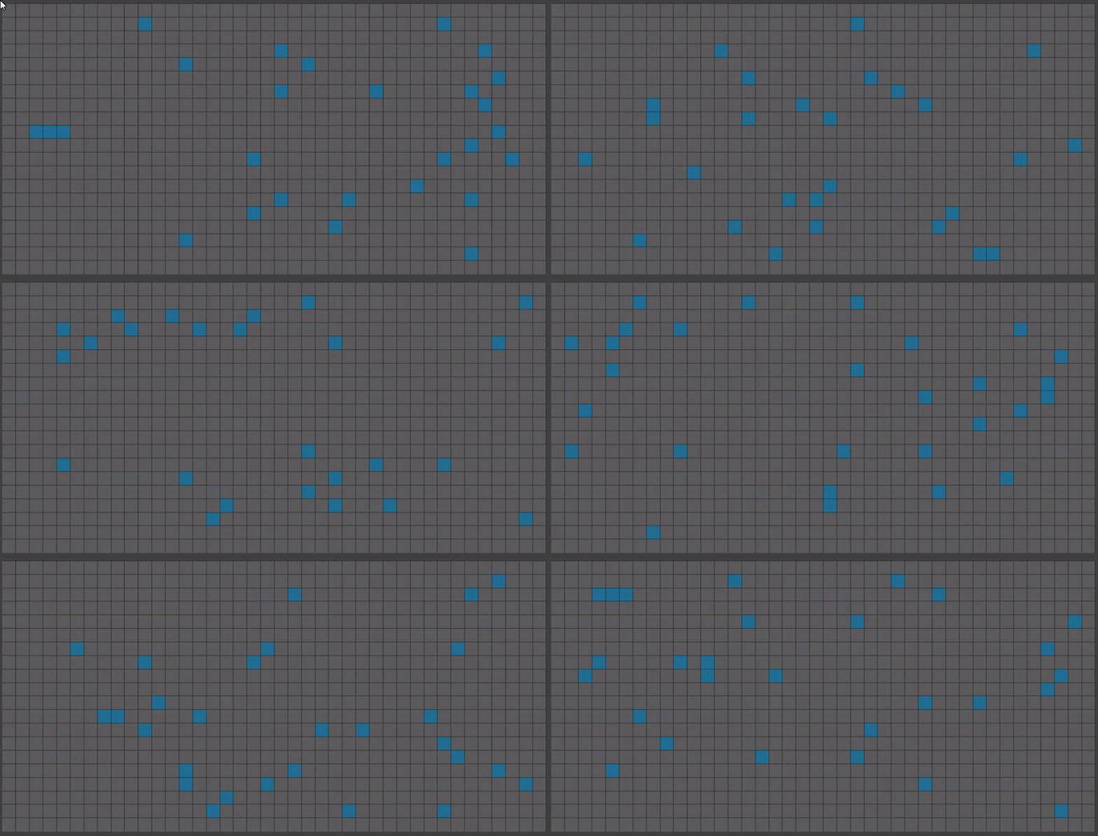
(4/15) Now, lets randomly place some pixels and store the coordinates of those pixels in a separate array. We want to avoid pixels being placed on the edges of our array, otherwise some algorithms we run later will have errors.
(Placed pixels will be shown as darker cyan from here on out.)
The pixels we place in this step, random or otherwise, will greatly modify the shape of our final land. I have found the best results use a mix of random and not random.
(5/15) These pixels aren’t very interesting on their own, and we don’t want random chunks of land. It’s time for our first algorithm! Yay!
Prim’s minimum spanning tree algorithm, or just Prim’s Algorithm1, will join all our pixels together to create a tree whose branches lengths are as small as possible. (We give it weights equal to the distance between pixels) Prim’s Algorithm doesn’t know how to actually convey its information onto our array of pixels though.
(6/15) Bresenham’s Line Algorithm2 has probably been the most critical algorithm in my entire project. What does it do? Draws lines of single pixel thickness! I modified it to write to boolean arrays instead of writing colors.
New color keys from here on out:
Black lines: Prim’s output
Cyan: Bresenham’s drawing Prim’s output onto our boolean array
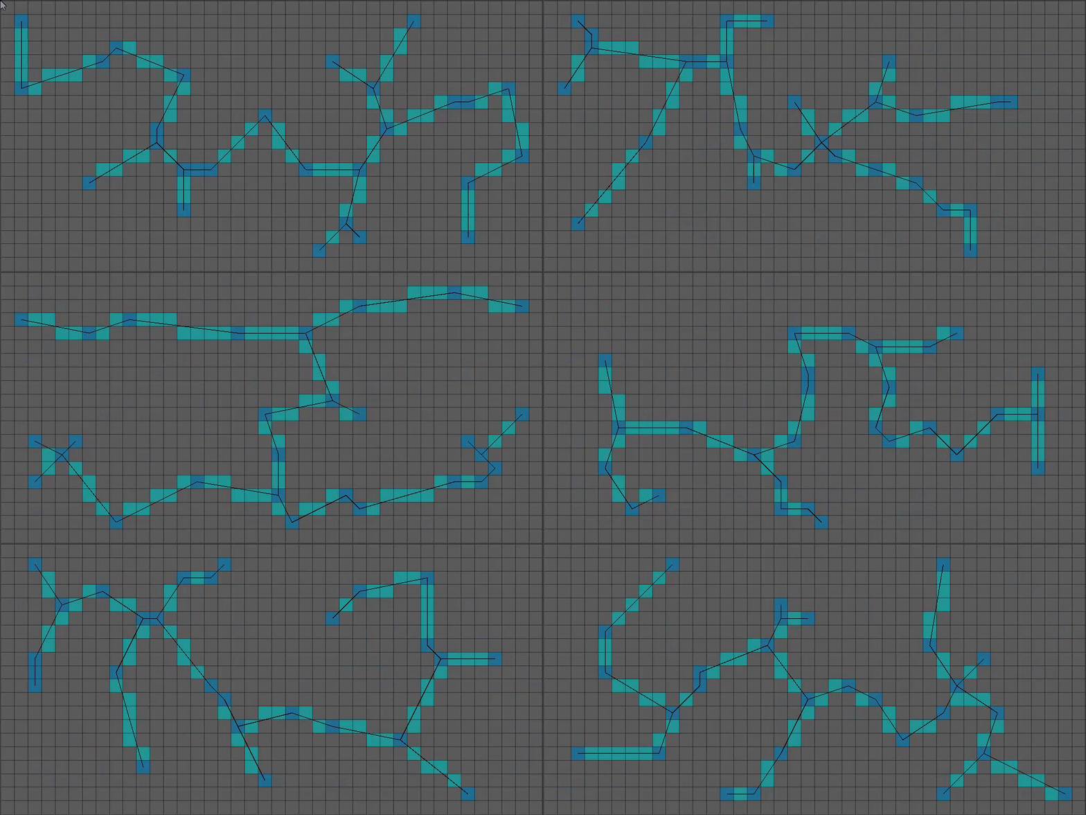
(7/15) That’s more interesting! It’s still a bit too thin.
Time for the growth phase! I just kinda did this part with my own code.
For X growth iterations, do the following for each pixel NOT on the edge of our array:
– Count cardinal neighbors with true values. If greater than one, add pixel coordinate to a new array.
– Once all pixels have been checked, iterate through our coordinate array and set the value in our boolean array to true.
That results in something like this: (Green = grown pixel)
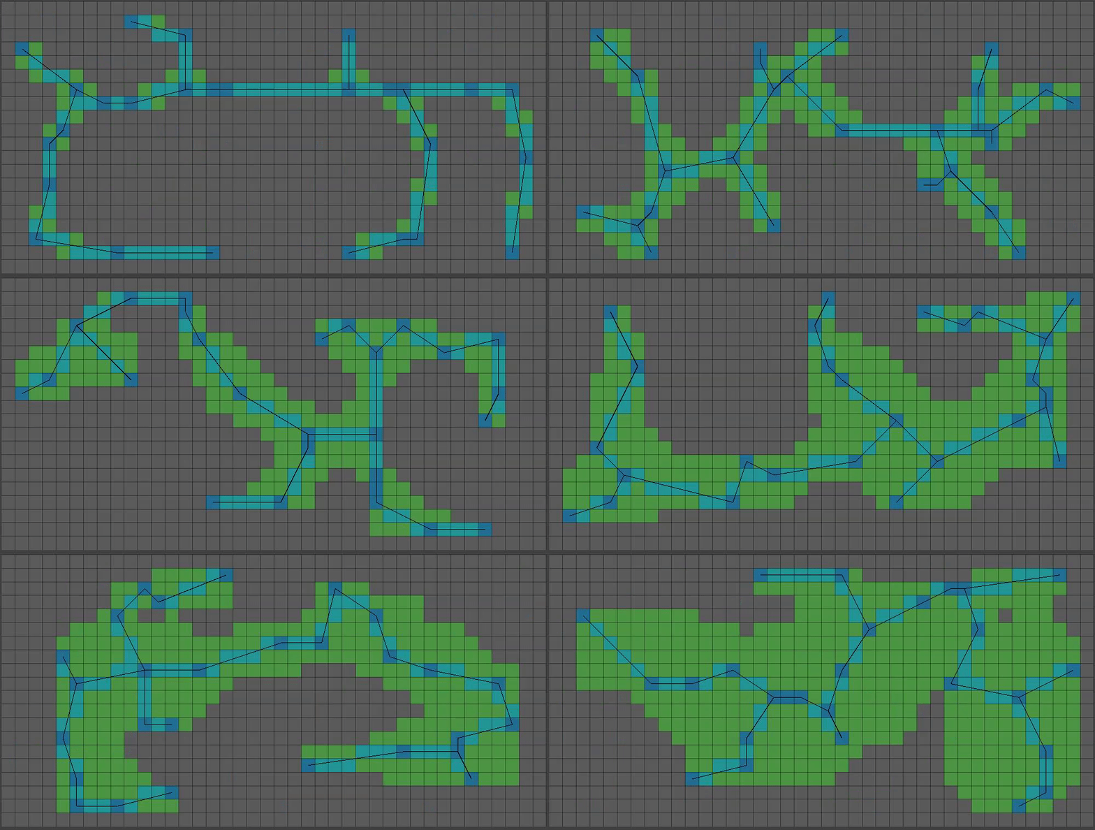
(8/15) You might have noticed a decrease in green pixels at the top of the grid. That’s because after a certain height, I only grow pixels that meet the requirements with a 50% chance. I also have a variable that will randomly grow pixels with only one solid neighbor, becoming less likely the higher the pixel is.
This is a bit too… floaty. Lets set some pixels at the bottom BEFORE our growth step. Also lets add bigger chunks of pixels (I prefer one chunk) to give a bit more “beef”:
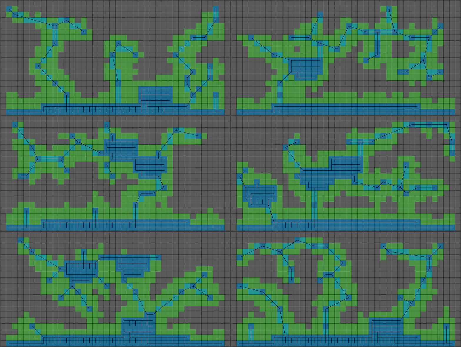
(9/15) That’s coming together! As far as the smaller boolean array goes, we’re done with messing with it. Time to start on the much bigger boolean array that will represent our final level’s collision data.
Before that, we are going to create another 2D array that represents the positions of shared corners, multiplied by an integer upscaleFactor. The size of our final level will be the size of our smaller boolean array multiplied by upscaleFactor.
(10/15) Next, an ugly part of my code, an IntVector2[,][]
That monstrosity is a 2D array where each X/Y index holds another array of IntVector2, specifically of length 4, to represent all four corners of any given pixel from our smaller boolean array.
I pass this data into our next algorithm: Theo Pavlidis’ Contour tracing algorithm3 which after given a single edge of a shape will return a list of positions of that shape’s edges.
(11/15) Can you guess what we do next? Yup, we feed all those positions into Bresenham’s line algorithm, but this time we draw on the larger boolean array:
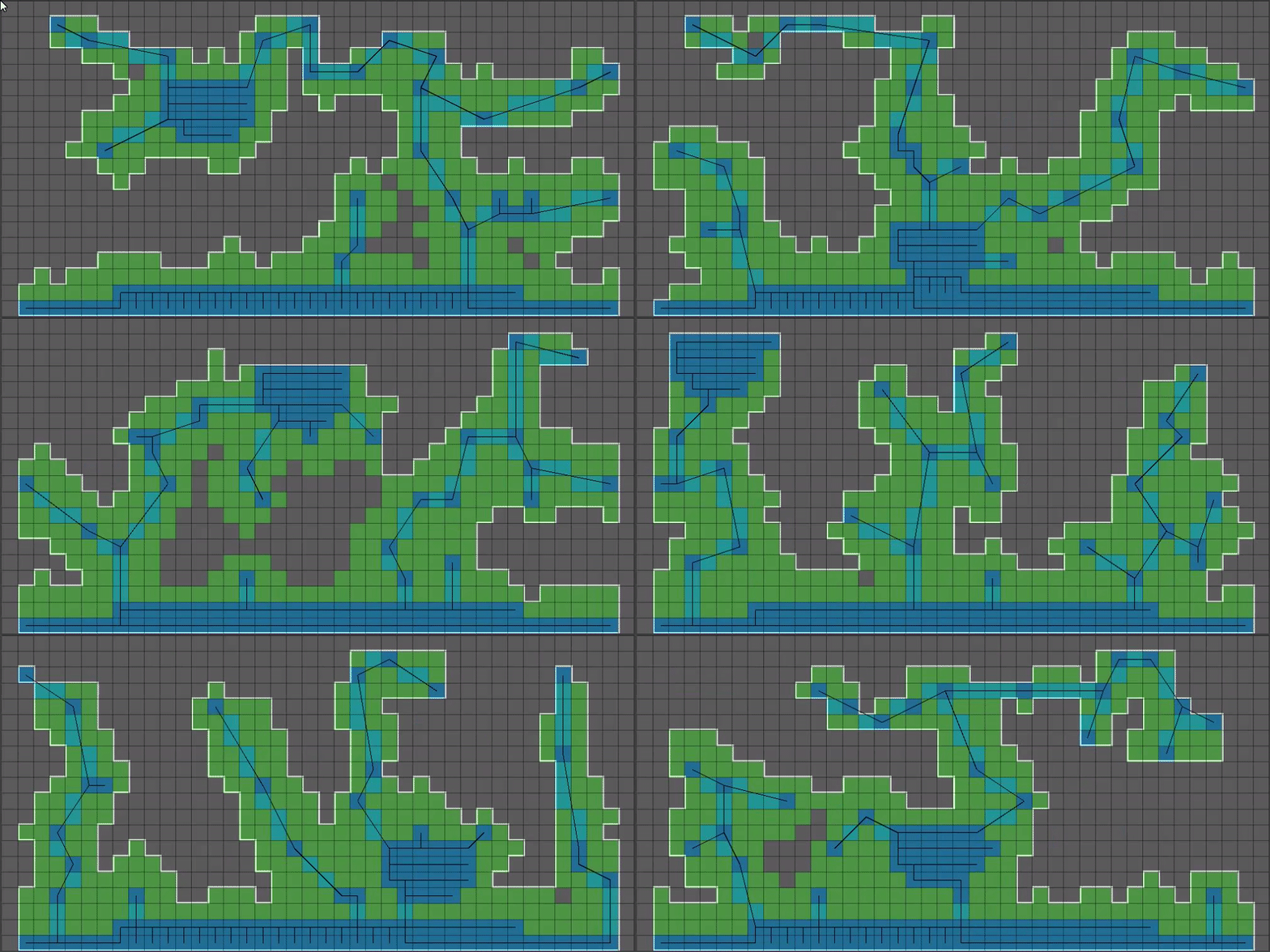
(12/15) That outline is a bit too blocky, so we’re going to introduce our final algorithm: Chaikin’s Curve Smoothing Algorithm4. This algorithm takes a set of points and makes a curve out of them, doubling the number of points it was given for each iteration.
Smoothing the above white outline using Chaikin’s gives us this:
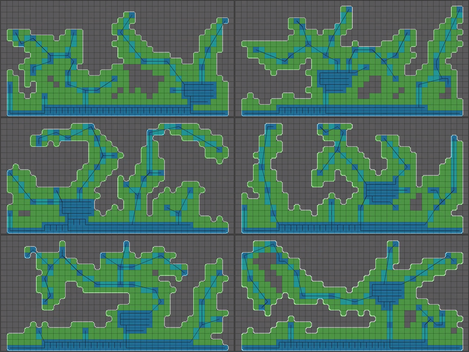
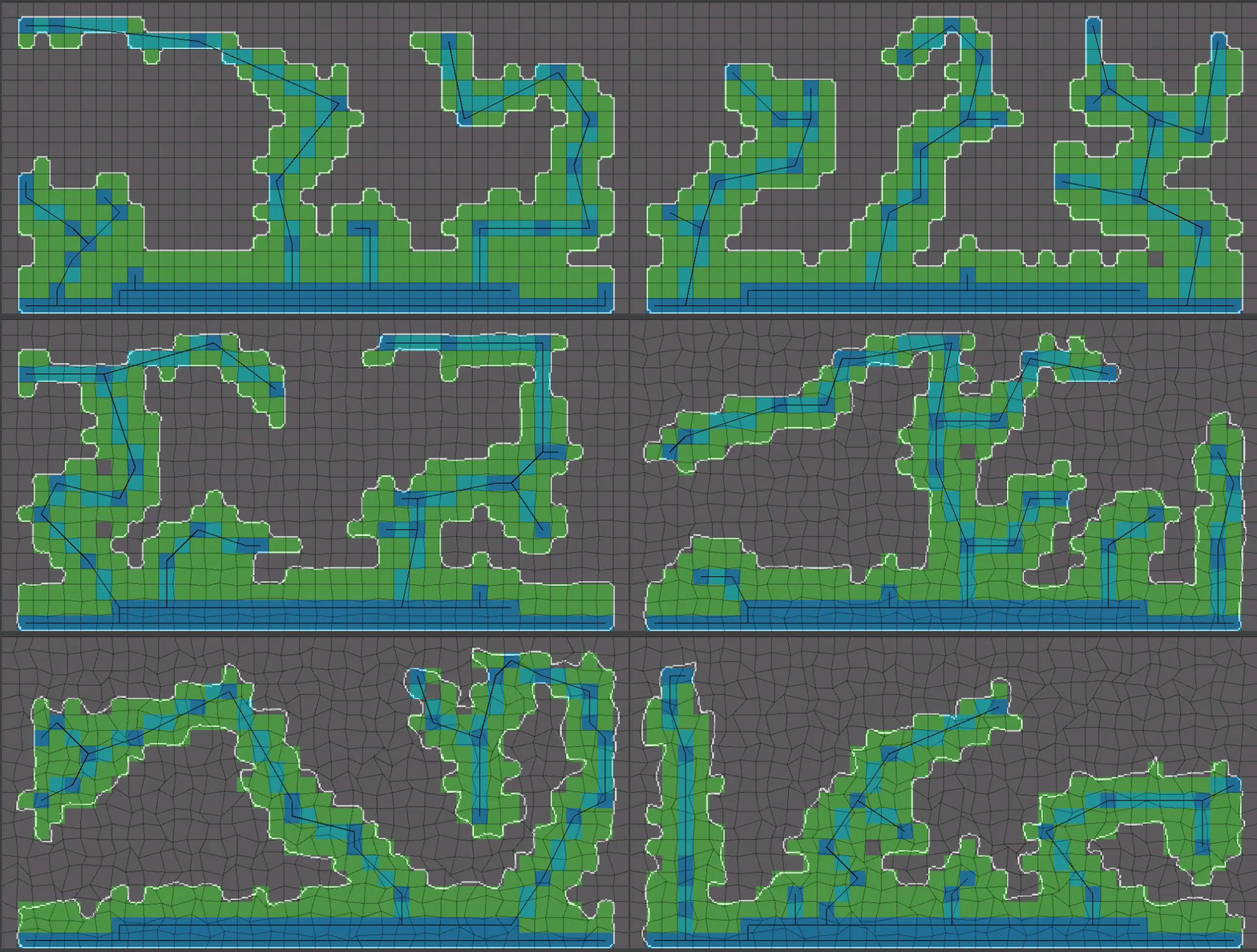
(13/15) Now for the real magic step that I left out of post 9 of this thread, for clarity purposes: When calculating shared corners of pixels, we are going to apply a random offset to each shared corner. The magnitude of the random offset MUST be small enough such that cell walls will not overlap, otherwise we are going to run into problems. For this reason I opted for a zero to one value for this setting.
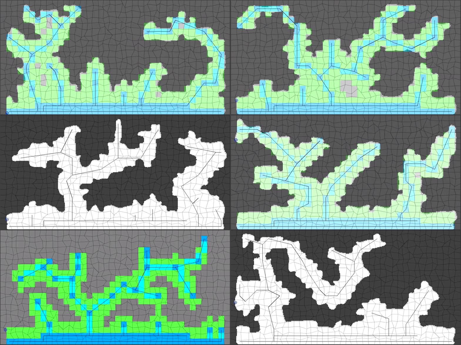
(14/15) The last step before we have something that can be used for gameplay: Flood fill inside of our shape’s outline!
Flood fill algorithms are a part of pretty much all image editors and for that reason I won’t be getting into that here. Flood fill will fail if our shape is not closed however!
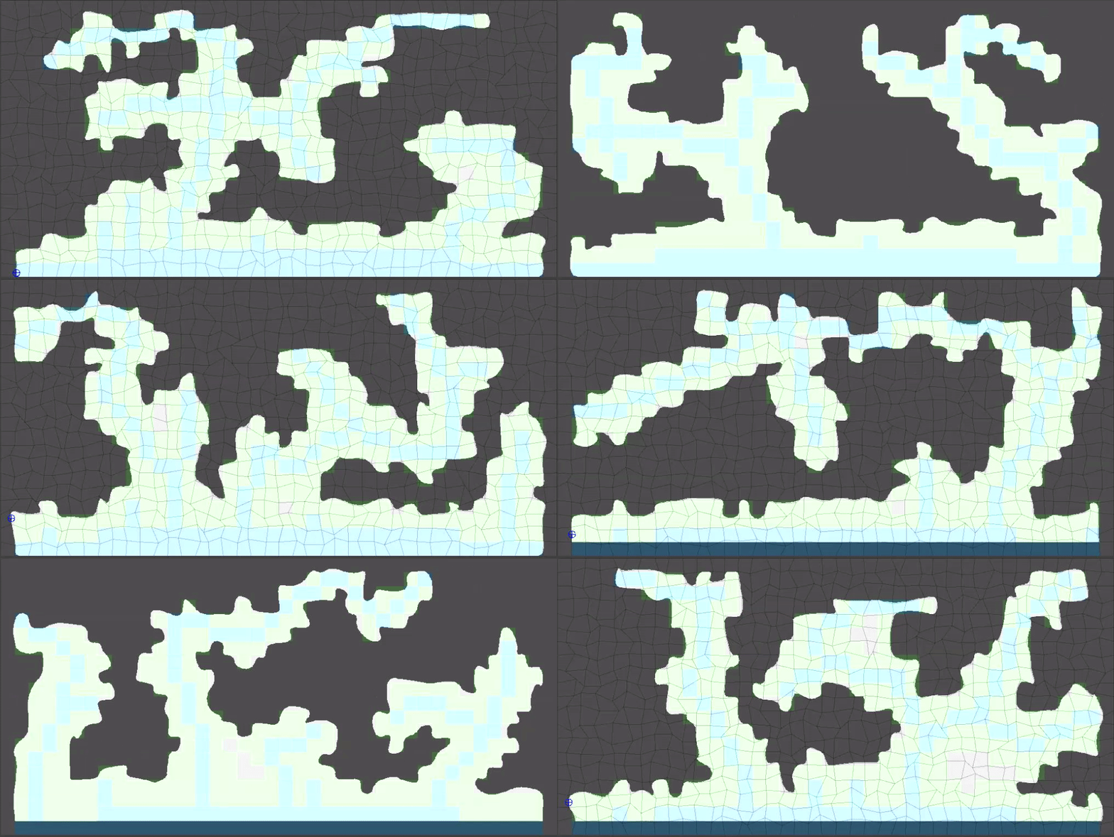
(15/15) The results look even better at larger values of upscaleFactor. So far in this tutorial I have been using an upscaleFactor value of 10 (400 x 200 image) but 30 (1200 x 600) is much closer to something that would be playable.
The last step that I will reveal for all of you here: Chop off the bottom most upscaleFactor pixels from the resulting level so that the bottom of the level looks more natural.
Hope yall found this helpful/interesting!
External Links
This was originally posted as a Mastodon thread on June 17, 2023.
- Prim’s Minimum Spanning Tree Algorithm: https://www.programmingalgorithms.com/algorithm/prim’s-algorithm/ ↩︎
- Bresenham’s Line Algorithm: https://en.wikipedia.org/wiki/Bresenham’s_line_algorithm
and https://www.codeproject.com/Articles/15604/Ray-casting-in-a-2D-tile-based-environment ↩︎ - Theo Pavlidis’ Contour Tracing Algorithm: https://gist.github.com/Smurf-IV/45236fc5531535e13b5debbc495c21dc
and https://www.imageprocessingplace.com/downloads_V3/root_downloads/tutorials/contour_tracing_Abeer_George_Ghuneim/theo.html ↩︎ - Chaikin’s Curve Smoothing Algorithm: https://www.cs.unc.edu/~dm/UNC/COMP258/LECTURES/Chaikins-Algorithm.pdf
and https://sighack.com/post/chaikin-curves and https://keithmaggio.wordpress.com/2018/05/29/math-magician-path-smoothing-with-chaikin/
and an interactive web version: https://observablehq.com/@infowantstobeseen/chaikins-curves ↩︎

 -
- 